Before Using the Printer
Part Names
Setup
Basic Operations
Cleaning
Troubleshooting
Appendix
Top > Part Names > Part Names
Part Names
|
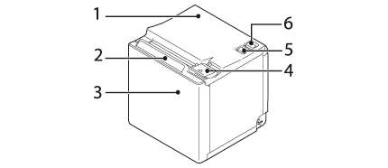
1 |
Roll paper cover |
Open this cover when installing or replacing the roll paper. |
|
2 |
Panel LED |
|
|
|
||
|
|
||
|
3 |
NFC Tag |
A mark is printed here to indicate the position of the NFC tag. To establish communication with an NFC device, bring the device close to this mark. |
|
4 |
Cover open lever |
Operate this lever to open the roll paper cover. |
|
5 |
|
Press this button once to feed the roll paper for one line. Hold down this button to continue feeding the roll paper. |
|
6 |
|
This switch turns the printer on or off. |
 Power LED: This turns on when the printer is on.
 Error LED:
 Paper LED: On indicates a paper out.
 Feed button
 Power switch
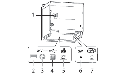
|
1 |
Knob |
Use this to manually move the autocutter blade. |
|
2 |
USB connector |
Use this only for the optional Wireless LAN unit. |
|
3 |
Power supply connector |
Connects the DC cable for the AC adapter. |
|
4 |
USB connector (Type-B) |
Connects the USB cable for connecting to computers. |
|
5 |
Ethernet connector |
Connects the 10BASE-T/100BASE-TX LAN cable. |
|
6 |
Status sheet button |
Use this button to print a status sheet on interfaces or initialize the settings on interfaces. |
|
7 |
Drawer kick connector |
Connects the modular cable for the cash drawer. |
The specifications vary by the printer model.
Before Using the Printer
Part Names
Setup
Basic Operations
Cleaning
Troubleshooting
Appendix
Top > Part Names > Part Names
Part Names
|
1 |
Roll paper cover |
Open this cover when installing or replacing the roll paper. |
|
2 |
Panel LED |
|
|
|
||
|
|
||
|
3 |
NFC Tag |
A mark is printed here to indicate the position of the NFC tag. To establish communication with an NFC device, bring the device close to this mark. |
|
4 |
Cover open lever |
Operate this lever to open the roll paper cover. |
|
5 |
|
Press this button once to feed the roll paper for one line. Hold down this button to continue feeding the roll paper. |
|
6 |
|
This switch turns the printer on or off. |
|
1 |
Knob |
Use this to manually move the autocutter blade. |
|
2 |
USB connector |
Use this only for the optional Wireless LAN unit. |
|
3 |
Power supply connector |
Connects the DC cable for the AC adapter. |
|
4 |
USB connector (Type-B) |
Connects the USB cable for connecting to computers. |
|
5 |
Ethernet connector |
Connects the 10BASE-T/100BASE-TX LAN cable. |
|
6 |
Status sheet button |
Use this button to print a status sheet on interfaces or initialize the settings on interfaces. |
|
7 |
Drawer kick connector |
Connects the modular cable for the cash drawer. |
The specifications vary by the printer model.