
Before Using the Printer
Part Names
Setup
Basic Operations
Cleaning
Troubleshooting
Product Specifications
Appendix
Top > Part Names > Connectors
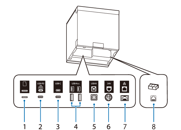
Connectors
The connectors are located on the back side of the printer. When connecting interface cables or other cables, remove the printer covers before connecting.
The type of installed interface and the number of connectors vary depending on the printer model. Check with your printer or refer to List of Installed Interfaces by Model.
See Checking the Product Name and Model Number for information on how to check the printer model.
|
1 |
microSD card slot |
For a special purpose and cannot be used for daily use. |
|
2 |
USB-C connector (USB-PD* compatible) |
Connects a USB cable to connect to a smart device such as a tablet device. Allows data communication while charging the smart device. |
|
3 |
USB-C connector |
For connecting a peripheral device such as a handheld scanner. |
|
4 |
USB-A connector |
For connecting a peripheral device such as a wireless LAN unit, customer display, or handheld scanner. |
|
5 |
USB-B connector |
Connects the USB cable for connecting to computers. |
|
6 |
Power supply connector |
Connects the DC cable for the AC adapter. |
|
7 |
Ethernet connector |
Connects the LAN cable. |
|
8 |
Drawer kick connector |
Connects the modular cable for the cash drawer. |
* The USB-PD interface is a USB-C connector that supports USB Power Delivery.
 CAUTION:
-
When a smart device such as a tablet or smartphone is connected to the USB-C connector (USB-PD compatible), the Bluetooth function of the printer is disabled.
To use the Bluetooth function while charging the device, you need to change the software settings. For details, see the Technical Reference Guide. -
Depending on the specifications of your smart device, it may not be possible to charge the device using the USB-C connector (USB-PD compatible). In that case, use a dedicated charger (such as the charger included with your smart device).
Before Using the Printer
Part Names
Setup
Basic Operations
Cleaning
Troubleshooting
Product Specifications
Appendix
Top > Part Names > Connectors
Connectors
The connectors are located on the back side of the printer. When connecting interface cables or other cables, remove the printer covers before connecting.
The type of installed interface and the number of connectors vary depending on the printer model. Check with your printer or refer to List of Installed Interfaces by Model.
See Checking the Product Name and Model Number for information on how to check the printer model.
|
1 |
microSD card slot |
For a special purpose and cannot be used for daily use. |
|
2 |
USB-C connector (USB-PD* compatible) |
Connects a USB cable to connect to a smart device such as a tablet device. Allows data communication while charging the smart device. |
|
3 |
USB-C connector |
For connecting a peripheral device such as a handheld scanner. |
|
4 |
USB-A connector |
For connecting a peripheral device such as a wireless LAN unit, customer display, or handheld scanner. |
|
5 |
USB-B connector |
Connects the USB cable for connecting to computers. |
|
6 |
Power supply connector |
Connects the DC cable for the AC adapter. |
|
7 |
Ethernet connector |
Connects the LAN cable. |
|
8 |
Drawer kick connector |
Connects the modular cable for the cash drawer. |
* The USB-PD interface is a USB-C connector that supports USB Power Delivery.
CAUTION:-
When a smart device such as a tablet or smartphone is connected to the USB-C connector (USB-PD compatible), the Bluetooth function of the printer is disabled.
To use the Bluetooth function while charging the device, you need to change the software settings. For details, see the Technical Reference Guide. -
Depending on the specifications of your smart device, it may not be possible to charge the device using the USB-C connector (USB-PD compatible). In that case, use a dedicated charger (such as the charger included with your smart device).